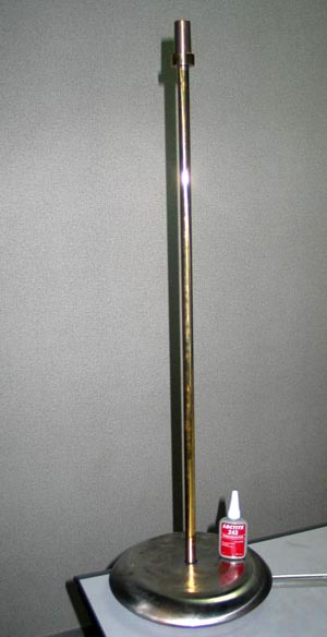
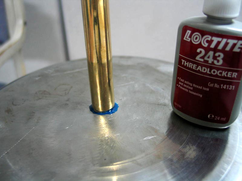
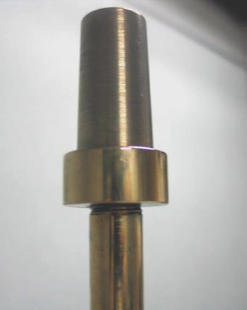
First you get the bottom of the rod threaded to fit the bob, if it isn't already so threaded. You should make a collar to fill the toroidal seat in the bob and screw it onto the bottom end of the rod tightly, right up to the bottom of the thread. [This detail is not illustrated, because the crude bob in the photos has no such groove.] Then you screw the rod into the bob, and the brass conical fitting member onto the top end of the rod, both glued on with thread-locker material ("Loctite" or similar, of the kind that you can break if you really want to). At this stage, the alignment does not matter.
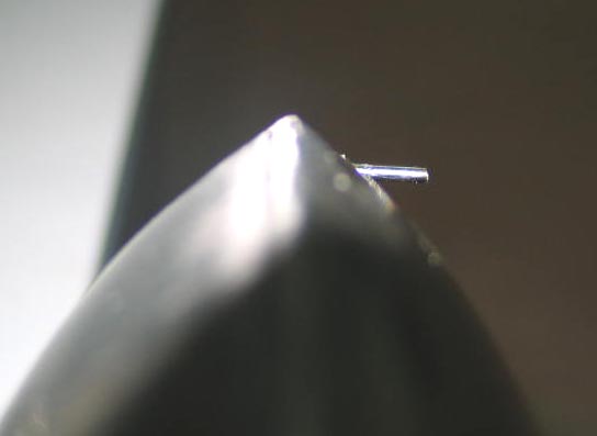
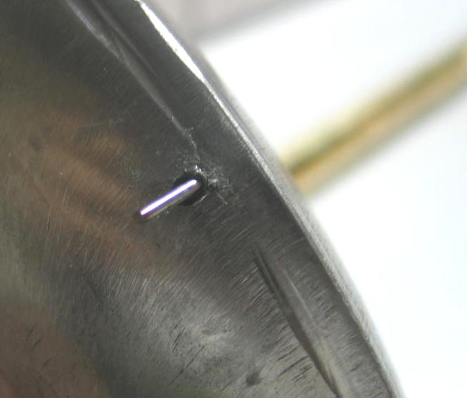
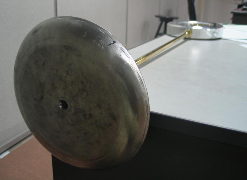
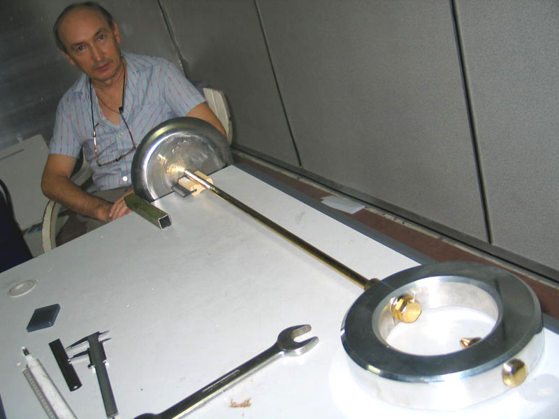
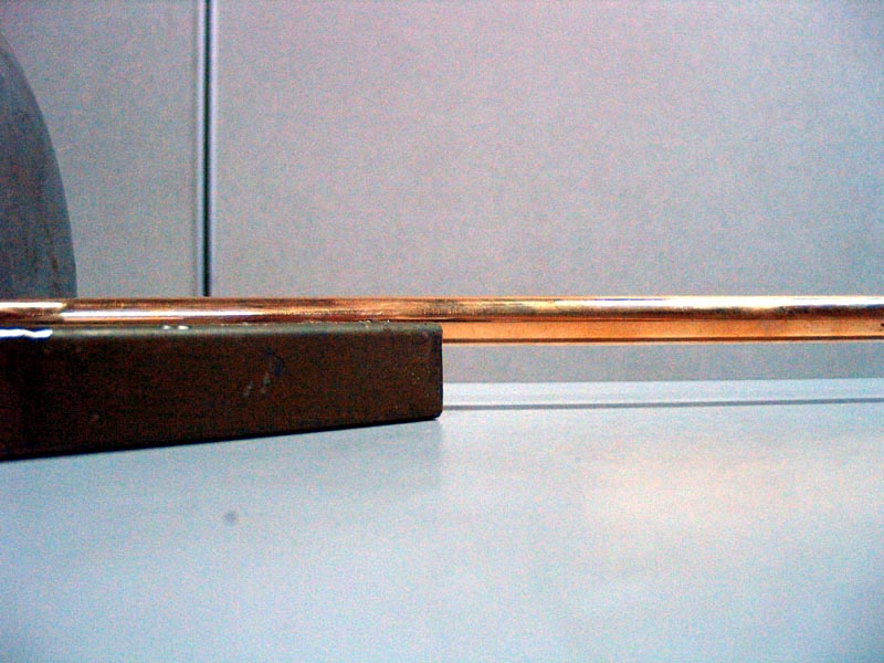
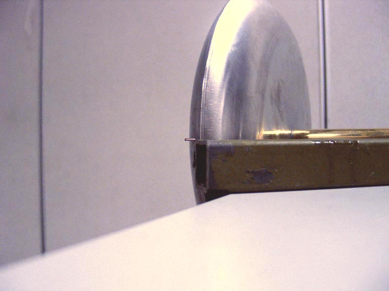
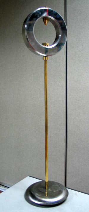
Now, the question is: how do you intend to release the pendulum? With a lenticular bob, I think that it is essential to pull out the pendulum sideways by holding it somehow at the edge of the bob which is a circumferential point, and not (for instance) by a central portion such as the rod or the pointer. The reason is that it is essential that the pendulum should start its motion in the plane which is preferred according to the Tennis Racket Theorem, i.e. in the same plane as the central plane of the ring, which is the plane perpendicular to the axis around which the pendulum has the greatest moment of inertia, I1. If (undesirably) this condition does not hold just after the pendulum is launched, then the pendulum will wobble about trying to get to it, and will eventually succeed after some chaotic evolutions which will have stultified the entire experiment. I have personally experienced this problem. Therefore it is unavoidable that some asymmetry will be introduced at the edge of the lenticular bob, in order to get a grip on it somehow. In my limited experience, the best such asymmetry consists of a little pin implanted near the outer edge of the bob and extending axially parallel to the pendulum rod. These photos show what has worked for me. It would be better to have two such pins at diametrically opposite sides of the bob, so that air resistance does not generate any turning moment on the bob (Allais did something similar; you can see it in his drawings.) The pin in the drawing needs filing down; it is far too long (and it is thicker than ideal as well). Next, you connect this assembly to the ring by fitting the conical member into the corresponding cone in the ring, and you tighten up the big bolt (30mm), but still leave it a bit loose. And you lay the assembly on a flat surface like a desk for jigging up. This photo shows the situation before you have rotated the bob and rod so as to line up the pin with the plane of the ring: You leave the bob hanging over the edge of the desk, and you prop up the rod with something of the right thickness so that it runs parallel to the surface of the desk: Then you get another lump of stuff of the right thickness just to reach up to the center of the rod as it lies there parallel to the desk: And you bring the other end of that lump of stuff over to where the pin is, and you rotate the bob and rod relative to the ring (by turning the conical fitting member in its conical seat in the ring) until the pin is in just the right place, like this: And then you tighten up the big 30mm bolt good and tight (working gingerly so as not to disturb the alignment). This clamps the fitting member tightly to the ring and thereby prevents rotation of the bob relative to the ring. Thus, finally, you have secured the bob to the rod, the rod to the fitting member, and the fitting member to the ring, so that the pin lies in the mid-plane of the ring, as closely as humanly possible. This shows the finished assembly: Done like this, you have a chance of making the Tennis Racket Theorem work for you instead of against you. Actually the pendulum does look a bit like a tennis racket on a plinth, doesn't it? Back to the description of setting up an English paraconical pendulum. Back to the website main page.